Phone and Network Overview
Cisco Unified IP Phones enable you to communicate by using voice over a data network. To provide this capability, the Cisco Unified IP Phones depend upon and interact with several other key Cisco Unified IP Telephony components like the networking device,i.e, a Cisco Catalyst switch and DNS, DHCP, TFTP servers, and other switches and also the IP Phone should be registered on the Cisco Unified Communications Manager system.
The following figure identifies the important parts of the phone.

Figure 1: Cisco IP Phone
- Programmable buttons: Buttons illuminate to indicate status or can be programmed as speed dial buttons,
 Green, steady—Active call or two-way intercom call
Green, flashing—Held call
 Amber, steady—Privacy in use, one-way intercom call, DND active
Amber, flashing—Incoming call or reverting call
 Red, steady—Remote line in use
 - Handset light strip: Red illumination indicates an incoming call or new voice message.
- Messages button: Auto-dials your voice message service.
- Directories button: Opens/closes the Directories menu. Use the button to access call logs and directory extension# of any employee.
- Settings button: Opens and closes the Settings menu. Use the button to change phone screen contrast, ring settings and to find the MAC address of the IP Phone.
- Services button: Opens and closes the Services menu. This button is used to guide the user to login screen to make use of the Extension Mobility(EMCC) feature.
- Phone screen: Shows call features. The above figure shows a Cisco 7961/62/42 screen, whereas the Cisco 7975/71/65/45 model provides a color screen.
The back of the Cisco Unified IP Phone includes these ports: Network port, Access port, Headset port and the Handset port.
Cisco Unified IP Phones and VLAN Interaction, Power
The Cisco Unified IP Phones have an internal Ethernet switch, enabling forwarding of packets to the phone, and to the access port and the network port on the back of the phone.
If a computer is connected to the access port, the computer and the phone share the same physical link to the switch and share the same port on the switch. This shared physical link has the implication of Data traffic present on the VLAN supporting phones might reduce the quality of VoIP traffic.Network security may need to isolate the VLAN voice traffic from the VLAN data traffic. You can resolve these issues by isolating the voice traffic onto a separate VLAN. The switch port that the phone is connected to would be configured to have separate VLANs for carrying:
- Voice traffic to and from the phone (auxiliary VLAN on the Cisco Catalyst 6000 series, for example)
- Data traffic to and from the PC connected to the switch through the access port of the phone (native VLAN)
The Cisco Unified IP Phones is powered with Power over Ethernet (PoE). PoE is provided by a switch through the Ethernet cable attached to a phone.
Cisco Unified IP Phone and Cisco Unified Communications Manager Interactions
Cisco Unified Communications Manager is an open and industry-standard call processing system. Cisco Unified Communications Manager software sets up and tears down calls between phones, integrating traditional PBX functionality with the corporate IP network. Cisco Unified Communications Manager manages the components of the IP telephony system—the phones, the access gateways, and the resources necessary for features such as call conferencing and route planning. Cisco Unified Communications Manager also provides:
- Firmware for phones
- Authentication and encryption
- Configuration, certificate trust list (CTL), and Identity Trust List (ITL) files via the TFTP service
- Phone registration
- Call preservation, so that a media session continues if signaling is lost between the primary Communications Manager and a phone
Cisco Unified Communications Manager Administration Phone Addition
You can add phones individually to the Cisco Unified Communications Manager database by using Cisco Unified Communications Manager Administration. To do so, you first need to obtain the MAC address for each phone.
You can determine a phone MAC address in these ways:
- From the phone, press the Settings button, select Network Configuration and look at the MAC Address field.
- Look at the MAC label on the back of the phone.
- Display the web page for the phone and click the Device Information hyperlink.
After you have collected MAC addresses, in Cisco Unified Communications Manager Administration, choose Device > Phone and search the device by selecting the Device Name, contains option from the drop down menu and enter the MAC address as shown in the below Figure 2.

Figure 2: Device search using MAC address
Click on Find and the Cisco IP phone connected to the network will show up in the search result. Now click on the device name link and the below screen will show up.

Figure 3: Device Information Entry
Enter all the necessary information and click on Save, Apply Config buttons at the top left to update the changes on the device. On the Phone screen, a maximum of 6 user numbers can be displayed including own number.The directory number setting and phone screen display setting for a user can be done by clicking on “Line[1] to Line[5]” under the Association section. Clicking on Line[1] will display the below screen.

Figure 4: Directory Number Information Setup
Enter the user extension/directory number, name and other required information. Scroll down to the Call Forward and Call Pickup Settings as shown in Figure 5. In case of forwarding all the calls to some other extension (Eg:when the user is on leave), enter the same in the Forward All section.The Call Pickup Group indicates that all the members in the group can pickup the call.

Figure 5: Call Forward Setting
Scrolling down further will take us to the Display Setting as shown in Figure 6. The entry made in the Line Text Label section will be displayed on the Phone screen. The External Phone Number Mask is the User Direct Access number from outside office and the masked area (XXXX) will automatically be filled with the last four numbers of the extension on the phone screen. Click on Save, Apply Config buttons at the top left in Figure 4 to update the changes on the device.

Figure 6: Display Setting
After the completion of the above settings,the Phone screen display will appear as shown in the Figure 7 below.

Figure 7 : Phone screen with User1 setting done
As we look at the screen ,we can observe the User name, direct access number, extension displayed as per the settings done. But, at the bottom of the screen we can see one more entry, i.e, the branch/office extension which we will be looking into from now on. The first step would be to click on Line [5] in the Figure 3 which will direct us to the following screen.
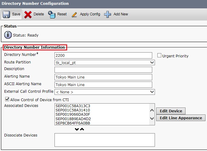
Figure 8 : Office Main Line Setting
The office extension should be entered in the Directory Number section and the other areas will be automatically populated if the number is already registered in the directory, else the other sections need to be corrected manually if already registered under a different name or need to be registered newly. Since new customers access the office number directly, all the frontline members need to have this setting on their respective IP Phones. The Associated Devices section indicates all the IP Phones having this particular setting and all the phones will ring once an external customer calls the office number.
Scrolling down will take us to the Call Forward and Call Pickup Settings, where none of the sections are touched except for the Call Pickup Group which will be the same as in Figure 5. This indicates that all the members in the group with this directory number setting on their IP Phones can pickup the call. Scrolling down further will bring us to the phone screen display setting as shown in the Figure 9 below.

Figure 9 : Main Line Display Setting
Input the Name to displayed on Line [5] in the Line Text Label section and the Office/Branch Main line number in the External Phone Number Mask section. Click on Save, Apply Config buttons at the top left in Figure 8 to update the changes on the device. So, when anyone calls the Office main line number, all the IP phones with this particular setting will ring and the respective programmable button next to the ‘Main Line’ will flash with Amber light indicating an incoming call.
Enabling the Special features:
- Addition of Expansion Module
The Cisco Unified IP Phone Expansion Module attaches to a Cisco Unified IP Phone 7962G, 7961G and 7961G-GE to extend the number or line appearances or programmable buttons on your phone. These phones support the Cisco Unified IP Phone Expansion Model 7914, 7915, and 7916. You can customize the button templates for the Cisco Unified IP Phone Expansion Module to determine the number of line appearances and speed dial buttons.

Figure 10 : Setting up of Expansion Module on CUCM
You can attach a Cisco Unified IP Phone Expansion Module 7914 to the Cisco Unified IP Phone 7961G and 7961G-GE by using the following methods:
When you initially add the phone to Cisco Unified Communications Manager (CUCM), you can choose 7914 14-Button Line Expansion Module in the Module 1 or Module 2 fields as shown in the figure above which appears as we scroll down from the Figure 3 screen. Another method is after the phone is configured in Cisco Unified Communications Manager.
When the Expansion Module is added, the Add On Module(s) section as shown in Figure 3 will be populated with Lines which can be updated with the user extension numbers.
- Extension Mobility
This feature allows a user to log into the Extension Mobility service on a phone by pressing the Services button and have the phone use the user’s phone number and user profile settings. Extension Mobility can be useful if users work from a variety of locations within your company or if they share a workspace with coworkers.

Figure 11 : Extension Mobility
The above screen appears once we scroll down from Figure 3 on CUCM. To enable the extension mobility we need to check the option as shown in the section(a) and once the user has logged onto to a different phone we can see the section(b) login information for that particular user.
- Do Not Disturb
This feature allows to mute the ringing and/or reject calls to an IP phone which may be helpful at times like when it is unused or when the user wants to just mute the ringing sound.

Figure 12 : DND Setting
On CUCM, check the Do Not Disturb option and select the appropriate item from the DND Option drop down selection as shown in the above figure, which shows up once we scroll down from the Figure 3 screen.
Cisco Unity Connection Administration
A tool used in most of the administrative tasks such as, customizing user settings and implementing a call management plan. This includes handling messages and distribution lists, managing audio formats, managing user passwords and PINs etc.
Cisco Unity Connection users are created to administer or provide access to the voice messaging system. The user attributes are the objects that enable you to control which users can connect to the system, and determine the system features and resources they can access. You can either manually add users or import them from the LDAP directory on the Cisco Unity Connection Administration page. Refer Figure 13 below right side window to Edit/Update User Basics setting.
Each user and administrator account that you add in Unity Connection is based on a user template. The user template settings include authentication rules and schedules. The authentication rules dictate the password or PIN and account lockout policy for the users that you create. You must review the settings in the user templates that you plan to use before creating a user account. This helps you to determine whether you need to make changes to an existing user template or create new user templates. For each template, consider the features that you want to enable, specify a class of service, set a schedule and time zone for the accounts you want to create.

Figure 13 : User Settings & Search
Cisco Unity Connection Administration allows you to find users based on search criteria that you enter. You can enter all or part of a name, extension, and/or user alias (ID) to find a user. In the above figure, we are using the extension number to find the user details.
Users with voice mailboxes are end users and the users without voice mailboxes are system administrators. Before you add user accounts individually, you need to select and define a template and class of service (COS) for each type of account you need to add. In case of end users, the default voicemail PINs and web application passwords are applied to each user account that you create. The voicemail PIN can be changed by clicking on Change Password as shown in the figure below.

Figure 14 : User Voice mail setting
Unity Connection comes with a set of default notification devices that can be configured as required. Following are the default notification devices:
- Pager
- Work Phone
- Home Phone
- Mobile Phone
- SMTP
- HTML
The default notification devices can be modified or enabled but cannot be deleted. An administrator can add, edit or delete additional notification devices whereas a user can only edit the notification devices.
Our point of focus here would be to setup SMTP Message notification as shown in the figure above. Cisco Unity Connection can notify a user of new messages by calling a phone or pager. Also, you can set up Unity Connection to send message, mail and calendar event notifications in the form of text messages to text pagers, mail address and text-compatible mobile phones using SMTP.
When a user observes red illumination on the handset light strip, it means that a voice mail has arrived. The user can press on the Messages button on the IP Phone and enter the voice mail PIN to listen to the voice mail.
Credits:
Experience
Knowledge
https://www.cisco.com/c/en/us/support/collaboration-endpoints/unified-ip-phone-7900-series/products-maintenance-guides-list.html
https://www.cisco.com/c/en/us/td/docs/voice_ip_comm/connection/10x/administration/guide/10xcucsagx/10xcucsag010.html#24744
Other online articles


Leave a Reply